The Power of Power Cable Verification for Offshore Wind
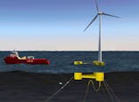
80% of all financial losses and insurance claims for offshore wind are caused by power cable failures (1). Independent verification is one step in the design phase that can have a significant impact on power cable reliability, yet few wind farm developers actively do it. In this blog, we will take a closer look at power cable cross section verification and the associated design checks that we recommend.
13 Jul 2023
Authors

Mike Campbell
Global Director, USA

Mike Campbell
Global Director, USA
About
Mike is a Global Director and vice president of 2H’s Houston office, where he is responsible for the management of the engineering group. Mike has over 22 years of experience dedicated to riser engineering, ranging from conceptual design and feasibility to detailed design, installation, monitoring and operational integrity management for all types of riser systems and subsea equipment. He has authored numerous technical publications including fatigue analysis methods and the use of field measurements to benchmark and improve design tools. Mike is a graduate of the University of Sheffield, UK, and has a bachelor’s degree in mathematics and physics.

Richard Harrison
Technical Authority

Richard Harrison
Technical Authority
About
Richard has 19 years of experience working in riser analysis and structural engineering. He provides advanced technical support and project management on innovative and technically challenging projects and is a consultant on many projects due to his history and experience in 2H. He has been involved in the implementation of various new analysis software programmes and the development of pre/post analysis software, including their use for renewables projects. He supports 2H’s wide range of in-house analysis tools and is responsible for developing new and bespoke features.
Richard is a graduate of Oxford University having obtained a DPhil in mathematical physics and a Masters in mathematics.
Expertise
Limited emphasis on verification in the industry
Some government agencies mandate a degree of verification for offshore wind structures; for example, the Bureau of Ocean Management (BOEM) in the US. However, the verification required is not prescriptive, consists predominantly of light-touch spot checks and does not provide any specifics for power cables. Thus, the onus is on offshore wind developers to decide their risk tolerance and determine strategies to minimise downtime.
In addition, current contracting strategies in the offshore wind industry tend to require suppliers to provide turnkey subsea equipment, including power cables, a practice that overlooks the need for and value of independent design verification.
Considering the failure statistics of subsea power cables and the costly consequences such as reduced power generation and equipment repair and replacement, conducting independent engineering due diligence prior to installation should be deemed a necessity. This straightforward activity could drastically reduce failure rates and maximise the operability of both fixed and floating offshore wind developments.
What needs to be verified?
This engineering due diligence can take many forms: independent verification of the power cable global design and analysis, verification of the power cable cross section response and performance, reliability modelling, failure mode and effects analysis (FMEA), testing and qualification, plus third party witnessing of these activities.
Steps in power cable cross section verification
When conducted by the suppliers themselves, the design of power cables and their cross sections is typically carried out using proprietary in-house tools. The functionality and validity of these tools is often a closely guarded secret which can exacerbate the risks to developers when using their equipment. These ‘black box’ tools make verification both more challenging whilst also highlighting the value of and rationale for conducting independent verification.
The activities we recommend for verifying power cable response based on cross section analysis include:
Modelling of cross section
Derivation of power cable properties such as mass, bending and axial stiffness
Capacity chart verification
Determination of crushing loads and installation hold back capacity.
1. Cross section modelling
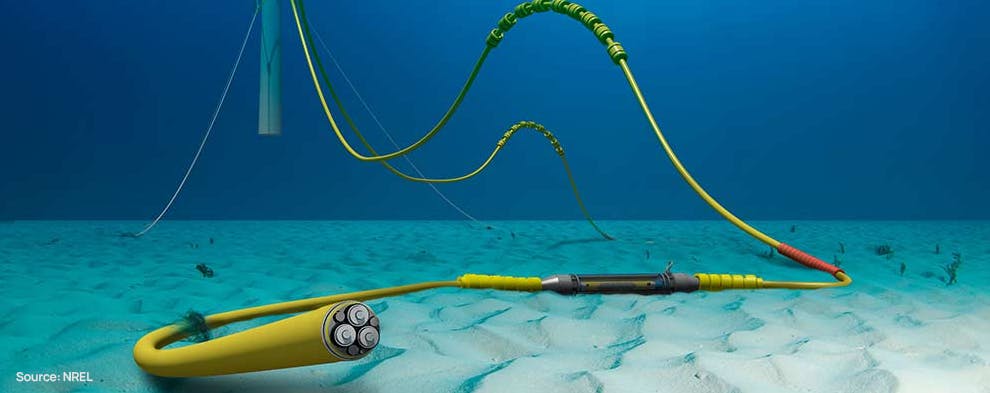
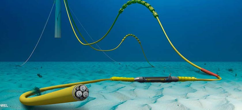
A typical high voltage power cable cross section consists of an HDPE outer sheath, with galvanised steel armour wire, with LLDPE inner sheath and polymeric fillers that hold fibre optical and three copper electrical power cables.

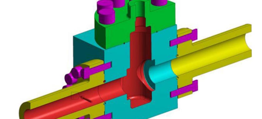
3D Breakdown of components inside the umbilical
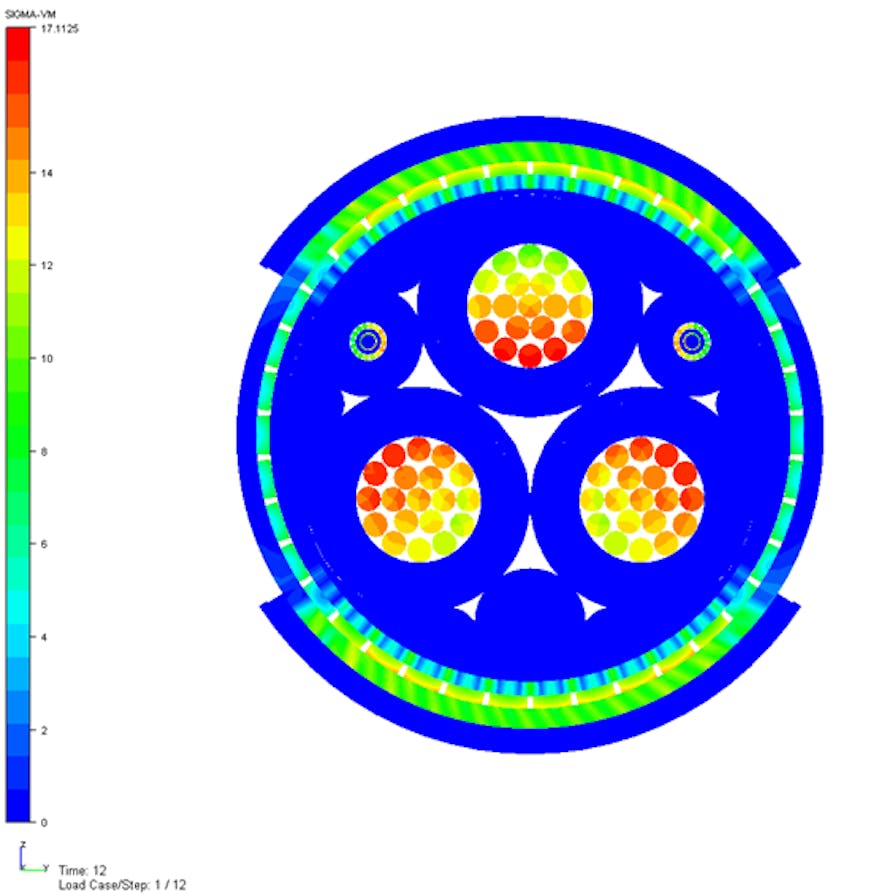
In this example, the cross section is modelled using the commercially available software, UFLEX (2). The UFLEX model includes all the cross-sectional features and their interaction including the pitch (torsional rotation along the length) of both the electrical lines and the steel armour wire. Pressure, bending and axial loads can then be applied. Example stress distribution plots are shown below of the power cable under bending and axial loading.

Von Mises of Umbilical under curvature (left) and under tension (right).
2. Power cable properties
Simulations utilising UFLEX are used to derive and verify the power cable properties. Key variables to be verified include the power cable mass, bending and axial stiffness.
3. Capacity chart verification
Analysis of the power cable cross section in UFLEX under a range of bending and tension loads can be conducted to determine the power cable capacity chart. Once derived, the capacity chart is used to define minimum bend radius (MBR) for the power cable, maximum allowable effective tension and the limits under combined tension and bending. These can also be used to verify the performance of the manufacturer’s stated storage and operating MBR values and tension capacity. The capacity charts are determined based on allowable stresses and strains in each of the components in the power cable cross section. Typically, stresses in either the armour wires or copper wires drive these limits.
The capacity chart below shows survival loading conditions compared to those of the vendor. In this example, the differences in performance are deemed small enough to accept the power cable design. The limiting components under tension are the copper wires, and under bending moment, the armour wires.
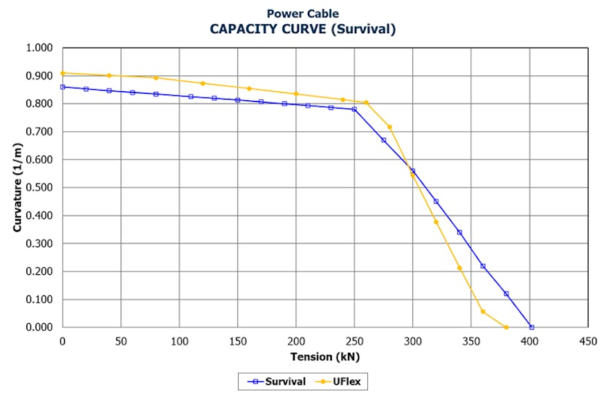
Survival Capacity Curve Comparison with Supplier’s Data
4. Crushing loads and holdback capacity
Allowable crush loads and holdback clamp capacities are used to define storage and transportation limits and confirm the suitability of power cable handling and installation tools. Exceeding these capacities can result in damage to the power cable’s outer sheath, water ingress and subsequent degradation of the power cable in service.
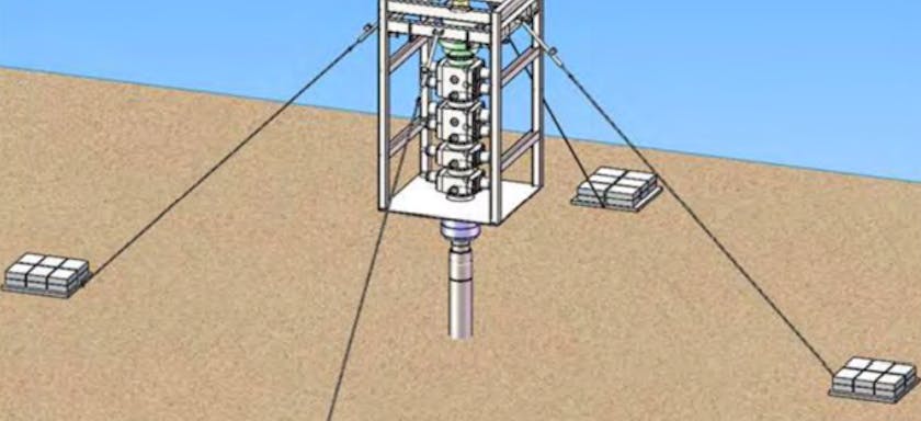
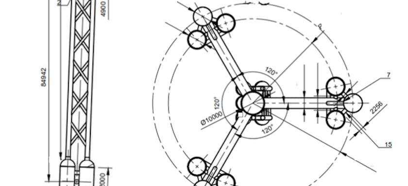
Simulation of crush and clamp loads are analysed using external contact faces. The clamping model example below shows that the umbilical was clamped using two 120-degree shells. Due to the distributed contact area from the clamp, the clamping load was limited by the stresses in the outer and inner sheaths. The target hold back tension can be combined with an assumed friction coefficient to determine the required clamp length which was verified to be 0.5m or more in this example.
Similarly, the crush load case is simulated using two flat plates and in this case the limiting parameter is the allowable strain in the outer sheath due to the concentration of power cable deformation. A calculated crush load of 130 kN/m was determined compared to 150 kN/m provided by the supplier indicating that the risk of damage during transportation and storage may be reduced by adopting a lower allowable crush load.
Clamping VM Stresses
Summary
There are several strategies to increase power cable reliability including confirming that the system design of the power cable is adequate through independent third-party verification.
With current turnkey contracting strategies and limited external recommended practices for verification, there is minimal emphasis on independent verification. Supplemental independent verification is a relatively low-cost exercise compared to the financial impact of power cable failures and could reduce failure rates and maximise operability of both fixed and floating offshore wind developments.
Verification can encompass a range of activities from testing, qualification, and independent local and global analysis. There is value in cross-section analysis using UFLEX and the typical design checks that can be conducted for independent verification. The design checks are used to confirm fitness for purpose, and limiting conditions for handling, storage and installation. Verifying the acceptability of power cable design for offshore wind developments can lead to improved reliability, reduced costs, improved efficiency, better decision-making, and increased flexibility.
Footnotes
1. Reference: LLOYD Warwick International Offshore Wind Loss Adjusters Perspective, 28 April 2021, ORE Catapult
2. More on UFLEX: UFLEX – Stress Analysis of Power Cables and Umbilicals - SINTEF
Authors
Mike Campbell
Global Director, USA
Mike Campbell
Global Director, USA
About
Mike is a Global Director and vice president of 2H’s Houston office, where he is responsible for the management of the engineering group. Mike has over 22 years of experience dedicated to riser engineering, ranging from conceptual design and feasibility to detailed design, installation, monitoring and operational integrity management for all types of riser systems and subsea equipment. He has authored numerous technical publications including fatigue analysis methods and the use of field measurements to benchmark and improve design tools. Mike is a graduate of the University of Sheffield, UK, and has a bachelor’s degree in mathematics and physics.
Richard Harrison
Technical Authority
Richard Harrison
Technical Authority
About
Richard has 19 years of experience working in riser analysis and structural engineering. He provides advanced technical support and project management on innovative and technically challenging projects and is a consultant on many projects due to his history and experience in 2H. He has been involved in the implementation of various new analysis software programmes and the development of pre/post analysis software, including their use for renewables projects. He supports 2H’s wide range of in-house analysis tools and is responsible for developing new and bespoke features.
Richard is a graduate of Oxford University having obtained a DPhil in mathematical physics and a Masters in mathematics.