
A Holistic, Proactive Approach to Platform Conductor Integrity
Imagine for a moment that you’re the technical authority for a fixed offshore platform and one of your regular 5-yearly visual inspections is underway. The contractor conducting the inspection has found significant damage to one of your conductors. By significant, they mean the conductor has parted at one of its connections near the splash zone and they can see the sky through the nearest guide. You have an integrity management plan in place, so how could this have happened?
3 Apr 2022
Author
Elaine Whitely
Senior Engineer, Houston
In this article, we will describe best practice techniques that will give you confidence that platform integrity risks can be safely controlled and ensure you have the information to prevent a similar situation from occurring on your asset.
Understanding the role and behaviour of the conductor
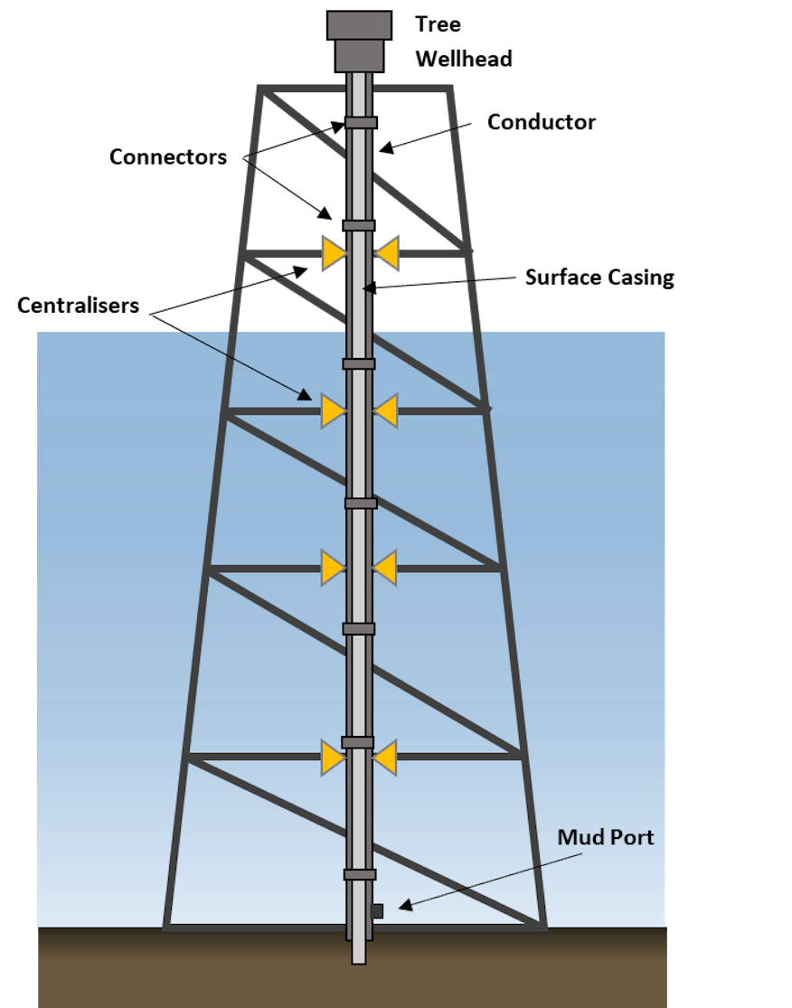
The first step in deciding how best to manage your conductors is to recognise what role they are performing. Every conductor acts as an environmental sheath, protecting the internal well casings from wave and current loads, but some conductors are also tasked with carrying the weight of the well itself.
The weight of the well is made up of the effective hanging weight of the casings and the production equipment sitting on top of it. This weight must be supported by something: either the conductor, the surface casing, or both, depending on the type of wellhead that is used and whether the surface casing was cemented back to the surface.
Knowing how the well is supported is critical in assessing any loss of condition because the axial load (amount of compression) the conductor is under controls how it responds to environmental loads. A conductor carrying a lot of well weight will be less stable, move more, and experience greater stresses under the same wave conditions than a conductor under less compression. Conductors under a lot of compression require more support from the platform structure. This support is usually provided by guides fixed to the platform. Think of it like tuning a guitar string: the tighter you wind it up, the less it moves when you pluck it and it will also produce a higher note (i.e. vibrate at a higher frequency).
To understand a conductor’s response, an assessment of its axial load is key. This assessment should account for the as-built casing tallies, drilling fluid weights, casing preloads, and top of cement heights achieved during well construction, as well as the internal pressures and temperatures during each planned well operation. This might sound excessive, but each of these things can greatly influence the effective well weight. Once you understand the behaviour of your conductor, the result of any loss of condition can then be assessed.
Most common issues with aging conductors
There are four common issues with aging conductors:
1. Loss of centralisation at one or more of the platform guides
Loss of centralisation is the most common initiator of a problem. Older designs, like the ‘thrust-collar’ type centralisers with a support ring welded to the face of the conductor pipe, are prone to fatigue damage due to the poorer quality of those welds. When this occurs, the centraliser can be lost completely or can hang up in the guide providing only some of the lateral support it was intended to. When the centraliser is lost, a chain reaction is initiated: the lack of support allows the conductor more freedom to move, this causes greater cyclic stresses in other components, in turn causing fatigue damage rates in those components to increase.
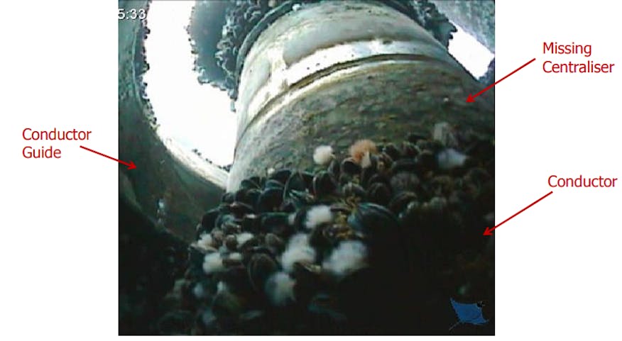
Missing centraliser on platform conductor
2. Fatigue failures, usually at a connector or a weld
Fatigue damage rates are usually of most concern in connectors because of the stress raisers in their geometry and/or the welds that join them to the pipe. Inspection photos often show connector damage in close proximity to a missing centraliser. If the weight of your well was meant to be supported by the conductor, the parting of a connector breaks this load path which means the surface casing might now be carrying more well weight than it was designed for, posing a strength and buckling risk. If this occurs, it should be addressed immediately.
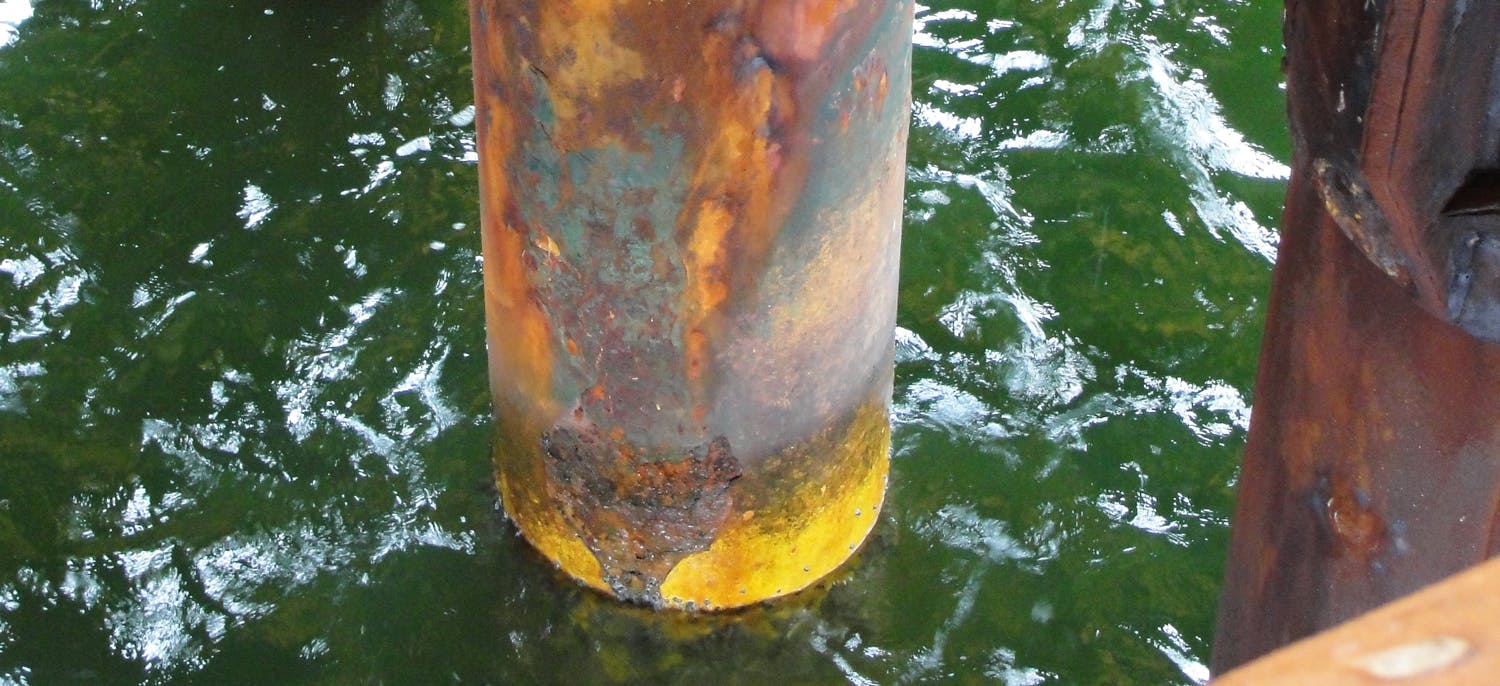
3. Corrosion from the seawater environment
Any fatigue damage is further exacerbated by corrosion as the conductor is exposed to seawater for the duration of its life. This can be managed at the design stage by including a corrosion allowance on the pipe wall thickness, but in warm environments and when the service life of the well is extended, these allowances can sometimes be exceeded.
Corrosion in the annulus between the conductor and the surface casing, however, may not have been considered during design. This space is sealed off from the seawater and should be a controlled environment, but it’s quite common for mud return ports at the base of the conductor to lose their seal and allow the annulus space to fill with seawater. This can cause faster corrosion of the strings carrying the weight of the well. Corrosion of the conductor itself can also cause such a breach if it goes undetected.
4. Change of service or service life duration not considered in the original design
Lastly, you also need to be careful when planning operations on a well that falls outside of the cases assessed during the original design. Operations to stimulate additional production, for example, may involve injecting cold fluids that will increase the effective weights of the hanging casings which will likely increase compression in the conductor.
Slipping through the cracks
The damage described above takes time to develop, so you may wonder why it’s not spotted sooner. In many cases, the answer lies in a lack of clarity around who has responsibility for managing the conductors. The conductor is a safety-critical element that has a structural function (to support the weight of the well), and a wells function (to protect the inner casings from the environment). It’s this dual purpose that leads to ambiguity. Wells people think the conductor is being managed by the structures team, the structures team think it’s being managed by the wells people. Of course, what’s really happening is the conductor is slipping between the cracks and not being managed by anyone, with damage not being identified until it’s critical. Oddly enough, this is a recurring problem that we have seen across many operators.
In truth, both disciplines have a role to play. The behaviour of the conductor is, as we’ve seen above, dependent on both what’s going on inside the well and the environment it is exposed to. It’s also dependent on how the conductor interacts with the platform so all teams need to be involved in the integrity management process so that the conductors can be assessed holistically to address all potential risks.
Reduce the risks with best practice integrity management
In practice, good integrity management is all about establishing effective communication across disciplines and between life-cycle stages of the well. This begins at the design stage which is when the IM plan should first be developed.
The plan should be based on a thorough understanding of the roles and behaviour of the conductors, as this allows the critical components of the system to be identified. For example, inspecting platform guides near the splash zone more regularly than inspecting guides near the seabed makes sense, because the upper guides have more of an effect on conductor behaviour.
The rationale for every recommendation in the IM plan should also be explained to the asset operations team after construction. This way, any changes to the integrity plan can be properly thought through. This might include updating the original design work, for example. It’s also important that any deviations to the well design during construction are fed back into the integrity plan, in case they change the criticality of certain elements and require changes to the inspection schedule. The same goes for different well operations. If a proposed operation will change the effective weight of the well strings, this should also be accounted for.
Finally, the inspection data generated by the plan needs to be interpreted, fed back into the plan, and stored in a way that makes it easy to access for all disciplines. The inspections are the main way by which in-field performance can be compared to design expectations and good data allows the IM plan to be updated and refined through the life of the field.
Hopefully, this article has shown how a careful approach and a clear understanding of structural concepts can help establish and operate a successful IM plan for platform conductors. These wells often need a little structural TLC along the way but a robust IM plan can help prevent such problems from developing before they become critical.
For specific guidance, 2H Offshore, along with Acteon companies, Clarus Subsea Integrity, Claxton Engineering, Pulse Structural Monitoring, and Core Grouting Services, developed the Guidelines for Integrity Management of Offshore Platform Conductors on behalf of the Energy Institute.
For help with a platform conductor integrity assessment, contact us.
Author
Elaine Whitely
Senior Engineer, Houston