
Maximizing Managed Pressure Drilling (MPD) Flexible Hose Operability
Over the past decade, managed pressure drilling (MPD) technology has evolved significantly towards becoming a standard offering on offshore drilling vessels. As existing deepwater offshore drilling vessels are upgraded to accommodate MPD technologies and “MPD-ready” rigs are brought into the fleet, one aspect that is often overlooked when conducting rig installation surveys is the hang-off locations of the flexible mud return hoses. The initial approach is usually to define the hose hang-off locations by minimizing piping lengths required between hose hang-offs and MPD control manifolds. Although this may seem like an intuitive approach to optimize cost and reduce installation time, it often results in poor operability and service life for the flexible hoses. Limited operability can reduce the operating conditions that the rig can drill in as compared to conventional drilling practices.
15 Mar 2021
Author
Suneel Patel
Principal Engineer, Houston
Based on a few of the key findings from 2H’s experience working with early adopters of deepwater MPD systems, this article provides guidance on how to maximize rig operability and reduce rig downtime by discussing the importance of several key design parameters of the flexible MPD mud return line hoses in the rig moonpool.
Overview of Managed Pressure Drilling (MPD) System
MPD enables drillers to overcome challenges when drilling deepwater wells. It allows the ability to precisely control the annular pressure profile to maintain wellbore stability, detect potential well kicks early, and provides the ability to safely manage any gas influx that may enter the marine drilling riser system.
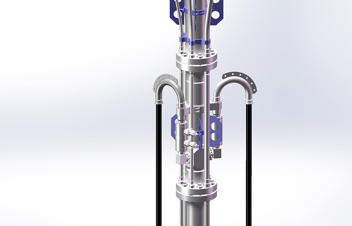
MPD operations require a specialized integrated riser joint, which is typically located below the drilling riser telescopic joint. The MPD integrated riser joint (sometimes referred to as the MPD joint) is typically broken up into four key sections:
Rotating control device (RCD), which serves as the primary means for sealing off the riser annulus during MPD operations
Annular blow out preventer (BOP), which isolates the riser annulus for servicing the RCD while also allowing the diversion of drilling fluids and gas influx
Flow spool, which diverts annular fluids through mud return lines (flexible hoses) to the MPD manifolds located on the rig topsides
Crossover adaptors, which interface the MPD integrated riser joint to the main riser pipe and/or telescopic joint
A schematic of a typical riser stack-up near the waterline, which encompasses an MPD joint, is shown below.
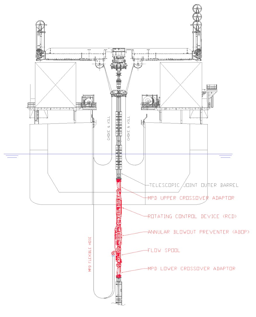
Depending on the riser stack-up and other rig- or project-specific requirements, the MPD joint may interface with a pup joint, spacer joint or a keel joint, which interfaces directly with the telescopic joint.
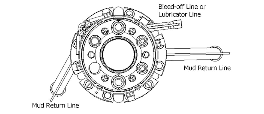
Since the MPD joint is designed to be at least as strong as the riser system itself, maximizing operability for MPD operations is dependent on the dynamic response of the MPD mud return line hoses. The MPD system diverts drilling returns to control manifolds located on the vessel typically through two flexible 6-inch mud return line hoses. Depending on the type of MPD system, a third flexible hose may be present to bleed-off pressure or to provide fluid to the control device.
The flexible hoses interface with the MPD joint in the flow spool region via a riser gooseneck.
Importance of MPD Mud Return Line Hose Length
The length of the mud return line hoses depends on the stroke range of the tensioner/telescopic joint and the elevation of the connection to the gooseneck on the riser stack-up. A shorter flexible hose poses a greater risk to the minimum bend radius (MBR) at the sag bend (or drape) than a longer hose when the tensioner/telescopic joint downstrokes. However, if the hose length is too long, then there is a risk the excessive drape of the hose may come into contact with the riser even in calm seas. To find the optimal length of each mud return line hose, it is recommended to determine the minimum hose length that satisfies the MBR criterion for the full tensioner/telescopic joint stroke range.
Gooseneck Position Should Not Be An After Thought
The orientation, or clocking position, of the riser gooseneck is also an important factor when determining operability, however, it is often treated as an after-thought. A poor riser gooseneck clocking position can result in excessive wrapping of the flexible hoses around the riser when the drilling rig weathervanes (rotates) or the hoses contact each other. To avoid damaging the riser system and to maintain the integrity of the flexible hoses, the riser gooseneck should be set in a clocking position such that the hoses are facing away from each other and the riser. If there is limited ability to adjust the orientation of the goosenecks, the adjustments should be made to the moonpool hang-off locations.
Determining Hose Operability Limits
Hose operability limits are determined to provide guidance to drillers to correlate hose design limits to real-time vessel operating conditions. To determine the operability limits of the MPD flexible hoses, engineers conduct three-dimensional dynamic finite element analysis (FEA). The global FEA considers a wide range of parameters, which include:
Environmental conditions (e.g., current speeds and wave heights ranging up to 10-year storm conditions)
Vessel conditions (e.g., movements with wave loading, vessel offset, weathervaning)
Flexible hose properties (e.g., outer diameter, weight per unit length, stiffness)
Flexible hose condition (e.g., seawater-filled with no internal pressure or mud-filled at working pressure)
Riser stack-up (e.g., use of spacer pup joints above or below the MPD joint in the riser stack-up)
Hose hang-off locations in the rig moonpool
The MPD hose manufacturer provides the design parameters that are used as input for the FEA. The following design parameters are key for determining the operability limits:
Minimum bend radius (MBR)
Maximum clashing energy with adjacent structures (e.g., riser, hoses, moonpool)
Maximum hose twist
Maximum axial tension along the hose length
An operating envelope is then generated by defining the limiting current speed and wave height combination in which the design parameters listed above are violated.
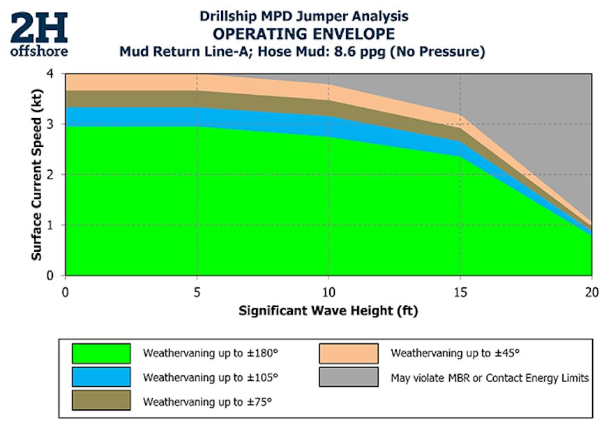
The sample operating envelope above shows the relationship between significant wave height (Hs) with surface current speed at a single vessel offset. The green region shows the allowable hose operability limits for vessel weathervane headings of ±180 degrees. The current speed and wave height limits can be increased by limiting the vessel weathervaning as shown by the blue, tan and orange regions. Increased vessel weathervaning typically results in MBR violations or excessive contact between the flexible hoses themselves or with the riser. The grey region of the operability envelope will likely result in the design limits of the flexible hoses being exceeded for all vessel headings.
The operability envelopes are typically generated either with the hoses seawater-filled at zero internal pressure (i.e., the hoses are installed, but no MPD operations are occurring) or with mud-filled hoses at maximum working pressure (i.e., during MPD operations). The hose stiffness decreases when it is not pressurized resulting in more movement, a lower MBR and/or increased clashing with adjacent structures. The seawater-filled hose with no internal pressure typically results in a smaller operating window and drives operability. This is the configuration drillers may be in when not using MPD during day-to-day operations or when experiencing extreme loading conditions. When MPD is in use and as internal pressure is applied to the hose, it becomes stiffer and more resistant to deflection from external loads, which increases the operability envelope.
Each flexible hose has its own unique set of operability windows. For an optimized solution, it is desirable to conduct analysis and refine hose placement and gooseneck clocking position so that each MPD hose has roughly the same operability limits.
MPD Hose Hang-off Locations are Key to Optimal Operability
The hose hang-off locations are the key to maximizing operability. Let’s look at three different configurations to understand how.
Configuration 1: Adjacent Hose Hang-off Locations
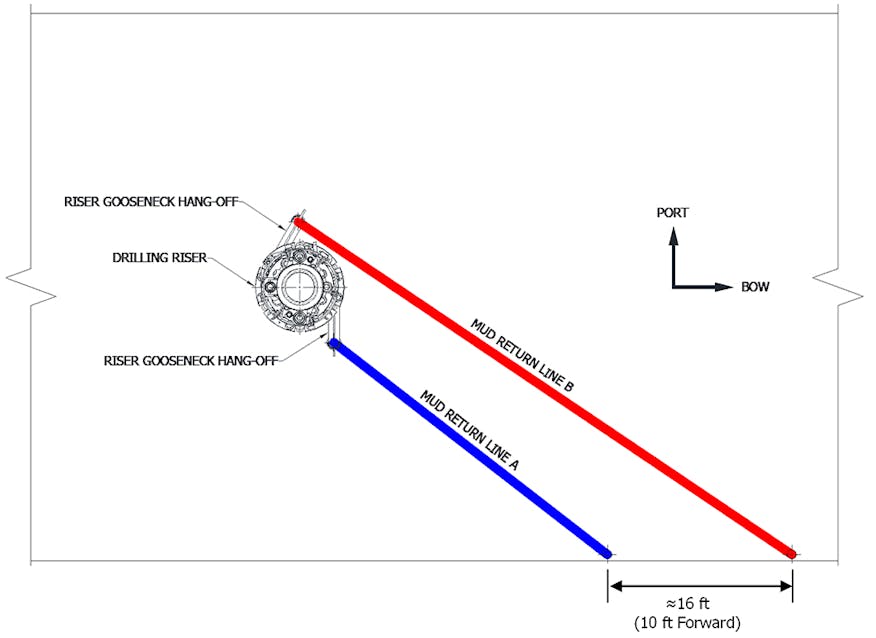
In our first scenario, we have minimized the required mud return line piping so that the hose hang-off locations are adjacent to each other (approximately 6 ft apart) and adjacent to the riser.

Additionally, the riser gooseneck clocking position is oriented such that Mud Return Line B is located towards the aft side of the riser. Due to the gooseneck clocking position in relation to the hose hang-off location, Mud Return Line B is guaranteed to come into contact with the riser even in calm sea states, which limits the operability envelope. The operability envelope for Mud Return Line B is shown below.
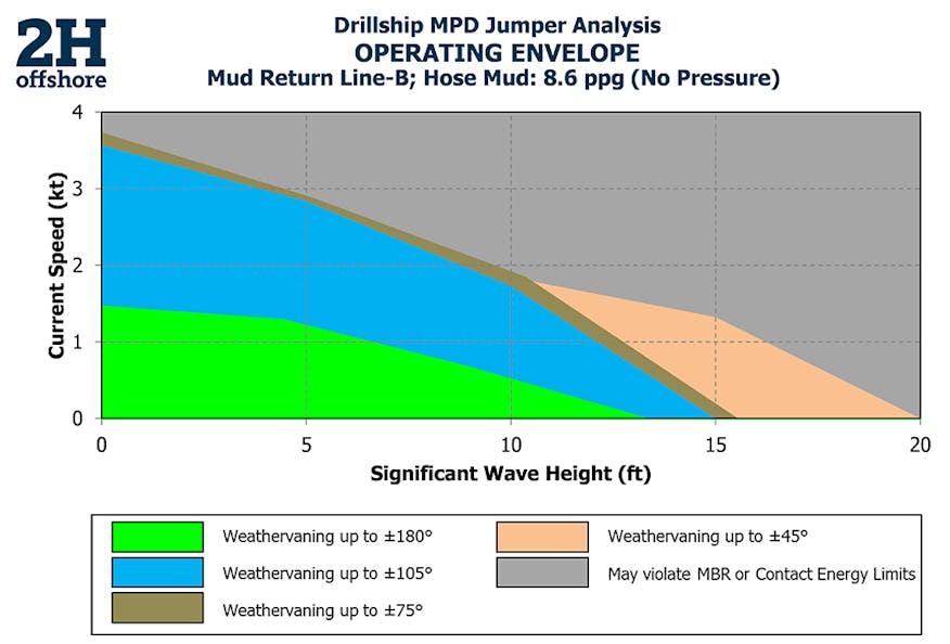
The limited operability for Mud Return Line B is driven primarily by two key design conditions:
The contact energy of the hose exceeding the design limits as Mud Return Line B comes into contact with the riser in all conditions as well as the adjacent Mud Return Line A in higher sea states.
The MBR of the hose being violated when contact occurs.
The resulting hose contact with adjacent structures such as the riser, adjacent flexible hoses or the vessel moonpool can result in structural damage. There are, however, mitigations to reduce the contact energy between the hoses and their adjacent structures, for example:
The use of hose bumpers near the riser gooseneck hang-off, which increase the contact diameter of the hose and forces the bumper to contact the adjacent structures rather than the hose itself
The use of a flexible hose sleeve, which works in a similar way to the hose bumpers, but can be placed near the sag bend of the hose body to mitigate the contact energy if the flexible hose contacts the riser
The use of bumpers on the moonpool edges
Although there was a minimal amount of mud return line piping used in this configuration, the cost savings are likely lost due to rig downtime and/or replacement of a damaged flexible hose.
Configuration 2: Mud Return Line Hose Moved Closer to Bow of Drillship
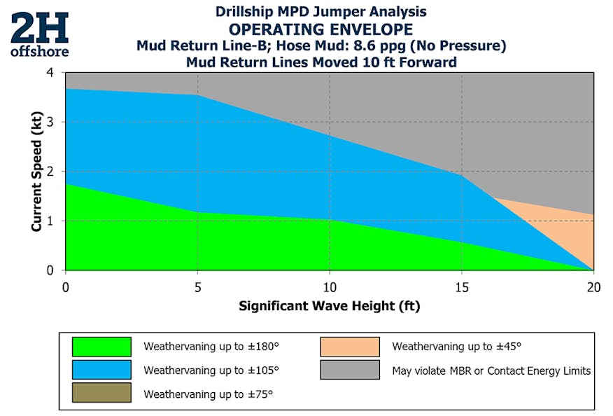
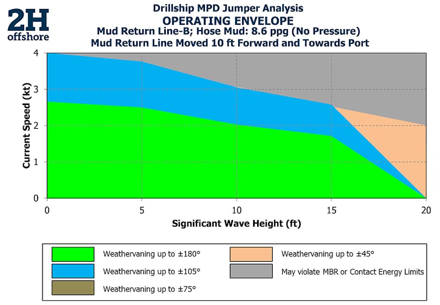
In this configuration, we have moved Mud Return Line B’s hose hang-off location approximately 10 ft forward in the moonpool as shown in the image below (i.e., 16 ft separation between the hang-off locations). Increasing the distance between the mud return line hoses will significantly decrease the likelihood of the two hoses coming into contact with each other. The forward movement of Mud Return Line Hose B will also reduce the contact between the hose and the riser, however, due to the riser gooseneck clocking position, contact between Mud Return Line Hose B and the riser is still likely to occur even in calm seas.
The resulting operability envelope for Mud Return Line B is shown in the image below. The operability is improved for vessel weathervane headings of ±180 degrees when compared to the initial hose hang-off locations in Configuration 1. Moving the hang-off locations forward typically results in improved operability as the likelihood of clashing with adjacent structures is reduced. Although the operability envelope has improved, the hose hang-off location can be further improved as Mud Return Line Hose B does still come into contact with the riser in calm seas.
Configuration 3: Mud Return Lines on Opposite Sides of the Moonpool
Based on the riser gooseneck clocking orientation, the best location to place the hose hang-off for Mud Return Line B would be on the port side of the vessel. Based on Configuration 2, moving the hose hang-offs forward results in improved operability. Configuration 3 moves the hang-off for Mud Return Line A forward by 10 ft and also moves the hang-off for Mud Return Line B to the port side of the drillship as shown in the image below.
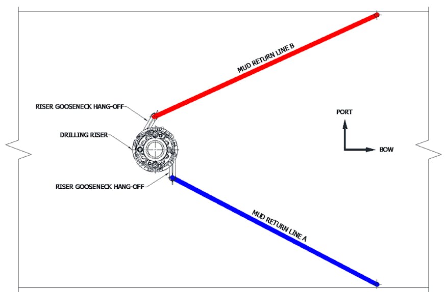
The resulting operability envelope for this scenario is shown below. Moving Mud Return Line B to the port side of the drillship significantly reduces the likelihood of Mud Return Line B coming into contact with the riser, and it also eliminates the possibility of the two mud return line hoses touching each other. As the likelihood of contact between the hoses and riser is reduced, the operability envelope is significantly better than those for both of the other configurations. Although it may not be the most cost-effective solution for pipe routing, separating the hose hang-offs such that one mud return line hang-off is on the port side and the other one is on the starboard side of the vessel will reduce rig downtime and risk of damaging the hoses. However, there is a potential downside to increased piping as it will generate additional friction losses when taking returns. The length of piping should consider flexible hose performance along with minimizing friction losses and piping erosion by balancing flow assurance.
Although the configurations described above consider hose hang-offs on the starboard and port sides, the hose hang-off locations can also be located on the aft end of the moonpool. This is more common on semi-submersible drilling rigs. In those configurations, it is important to maintain adequate distance between the mud return line hoses. It is recommended to have one mud return line towards the port side of the aft and the other towards the starboard side of the aft.
Maximizing Operability
While developing MPD-ready drill rigs, the earlier drillers can look at MPD pipe routing and hose hang-off locations on the vessel, the better it is for minimizing rig downtime. To maximize the operability limits for the flexible hoses, the following should be considered before operations:
The riser gooseneck position relative to moonpool MPD hose hang-off locations
Adequate spacing of the hose hang-offs with respect to the riser:
If hose hang-off locations are located closer to the riser, it reduces the separation between the hose connection points resulting in an increased likelihood of MBR violations
Increasing spacing of hose hang-off locations away from the riser helps to improve the natural sag of the hose resulting in a reduced likelihood of MBR violations
Adequate spacing between the mud return line hang-offs in the vessel moonpool:
If port/starboard side hang-offs are required, it is optimal to have one mud return line hang-off on the port side and the other one on the starboard side.
If aft hang-offs are required, it is optimal to have one mud return line towards the port side of the aft and the other towards the starboard side of the aft.
If both hose hang-offs must be located on the same side of the moonpool, increased separation between mud return hose hang-offs reduces clashing between hoses.
Hose lengths are determined based on the tensioner/telescopic joint stroke. It is both cost and operationally effective to have an optimal hose length to avoid excessive contact with the riser.
The use of swivels on at least one end of the hose allows for the flexible hoses to articulate freely and avoid any MBR issues at the hang-off locations.
The use of hose bumpers or protective coverings can be used to prevent the hose from damage from clashing and abrasion.
2H Offshore has an extensive track record offering a variety of services for getting drilling rigs ready and certified for MPD operations. Some services include the design and delivery of MPD crossover joints and the development of operability envelopes to mitigate risk of rig downtime. Visit our drilling riser page to see our range of drilling riser related services.
Register for our upcoming webinar: Key Challenges of Managed Pressure Drilling Riser Stack Integration
Author
Suneel Patel
Principal Engineer, Houston