Managing the risk of fatigue failure for workover or P&A can be complicated by a number of factors:
1. A lack of as-built data about the well and previous drilling operations.
2. Less fatigue resistance than in modern wells.
3. The use of larger, heavier modern BOPs on obsolete equipment.
In this article, we’ll talk about some of the methods now being used to tackle these issues, so that you can execute your operations with confidence that fatigue risks are safely controlled.
Addressing the lack of well and operational data
The first step in assessing whether sufficient fatigue capacity remains is to define what sufficient capacity actually looks like. This depends on what operations you plan to conduct. A live well re-entry, where you expect communication with the reservoir, will require a greater residual fatigue capacity than a casing removal once the well has been plugged, for example. Several well-established software tools exist for analysing this residual capacity. Whichever tool is used, the approach must consider what information is available about previous operations. This includes the vessel used, the length of the campaign and the weather in which it was conducted. Complete data sets are rare so you’ll probably need to make pragmatic assumptions to fill in any remaining gaps. For instance, if the dates of previous operations are known, the weather experienced can be estimated using hindcast modelling. This can include combined directional and seasonal effects which together can change fatigue damage results significantly. Also, disconnect periods, riser tensions and mud weights can usually be found in daily drilling or end of well reports. The effects of these inputs may be less significant than weather effects but are still valuable to you in ensuring the accuracy of the result.
Accounting for fatigue resistance of old equipment
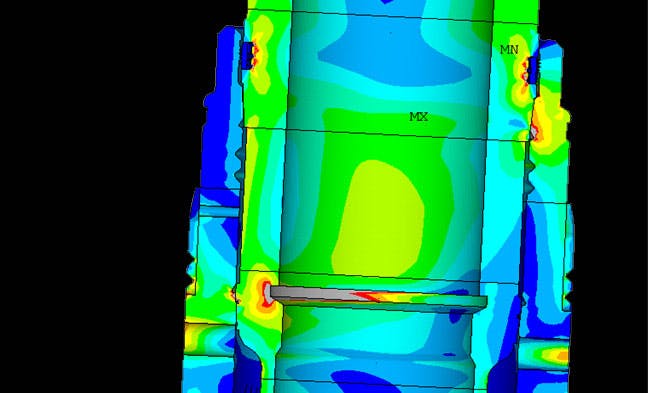
Another area of uncertainty for old wells is the fatigue resistance of the wellhead equipment you are connecting to. You may find obtaining any fatigue design data (i.e. stress concentration factors (SCF) and SN curves) for specific components to be difficult, as this information wasn’t recorded for many older designs. Assumptions may be made in these situations – based on judgement and experience – but as the outcome of the fatigue assessment is very sensitive to these inputs this must be done with care. Doubling the SCF in a wellhead housing can lead to a 16x – 32x increase in fatigue damage, for example. Methods of determining these inputs do exist, although each has its limitations. Detailed finite element analysis of the component can be used to calculate SCFs if you can obtain the necessary geometric information from the manufacturer. Alternatively, if you have spares available, fatigue testing can be conducted if it is cost effective to do so.
Using structural monitoring data to calibrate analyses
If the analysis doesn’t prove performance on its own, you can turn to structural monitoring data as a means of building confidence in the equipment’s fatigue capacity. In recent years, many operators have moved towards complex, online structural monitoring systems. In the majority of cases, such complexity is unlikely to be required and it may even provide you with misleading information. Trusting the outputs of these systems, prior to using the recorded information to confirm the accuracy of the model, can underestimate fatigue damage rates. Uncertainties such as the stiffness of the soil around the well can have a significant effect on how the model responds and, in turn, the fatigue damage rates associated with different sea conditions. Calibrating the model by tweaking these inputs and bringing the response into line ensures that your fatigue damage rates are calculated correctly. Retrofit and readily retrievable sensors, coupled with efficient data processing of the retrieved data onshore, are just as capable of providing the information required to perform the necessary calibration steps.